
Looking back on the first version of our machine hack, it is working but not very elegant yet. There are some issues to address in a version 2 focussing on reliability and ease of use. This will be important especially if we want to try out our hack with a group of people that are not involved in our pilot – which we will do during our Waag Open public event, where we will invite local people to make their own tools to use in our machine hack.
We asked Sven Dekker, our previous intern in the Fablab (who also happens to study engineering), to develop this second tool holder based on the issues we had with the first tool holder. You can find his documentation here and below.
lessons learned from tool holder 1
We have tried out multiple tool-to-toolholder connection methods during the first version of the machine hack development:
- bolts and threaded inserts to balance tools when centering was not necessary
- fixed size 3D printed clips
- foam tape as a DIY method when centering a tool was needed
- iris mechanisms as a more robust centering method
Since the main focus for continuing the machine hack is to make an interactive tool that is easy to use, the first two options are not the best approach, since they don’t really work in a system where a tool needs to be centered and where the tool diameter is variable. The foam tape was only a temporary solution, and does a bad job at keeping a tool perfectly centered. The iris mechanism looks the most promising, but we haven’t implemented it in a tool holder yet. We have printed a scaled down version of this compliant iris mechanism and that worked pretty nicely, except for that the pins to keep the two parts in place snap off really quickly. We have found other examples of iris mechanisms that are used for plotters, like this one for a Tevo Tornado 3D printer.
Next steps
For the second version of the tool holder, we are asking ourselves how can we make a tool holder for the interactive tool holder that is:
- easy to use (i.e. snaps in place instead of requires a lot of tweaking of nuts and bolts)
- centers tools reliably in a electronically controlled swinging and revolving tool holder (i.e. the tool holder should make sure that the tool is automatically centered, not the user)
- is stable in all directions (i.e. X and Y directions do not wobble, Z direction pressure is even and can be controlled, has a safety mechanism like a spring to make sure that brushes are not ruined)
- not super bulky and heavy
The ultimate goal is to create an interactive, universal tool holder that seamlessly integrates composite motions with user input and allowing for easy tool interchangeability. Below are the design criteria points we discussed that we needed, as summarized by Sven:
Design Criteria:
-
Develop in Fusion 360: The tool holder must be designed using Fusion 360 to ensure Waag Futurelab can easily access and modify the design after my involvement.
-
Adaptable, Self-Centering Mechanism: The design must accommodate tools of varying diameters (with a max of 32mm) and lengths, allowing them to be installed and automatically centered within the holder.
-
Composite Motion: The holder should support two types of motion—swinging/rotating along the y-axis and revolving around the z-axis.
-
Design Constraints:
- The attachment point must align with two predefined screw holes.
- Two servo motors need to be embedded to control motion in both axes (y and z).
- The overall size must fit within the constraints of the AxiDraw plotter.
- The tool holder must be durable enough to withstand upward pressure during operation.
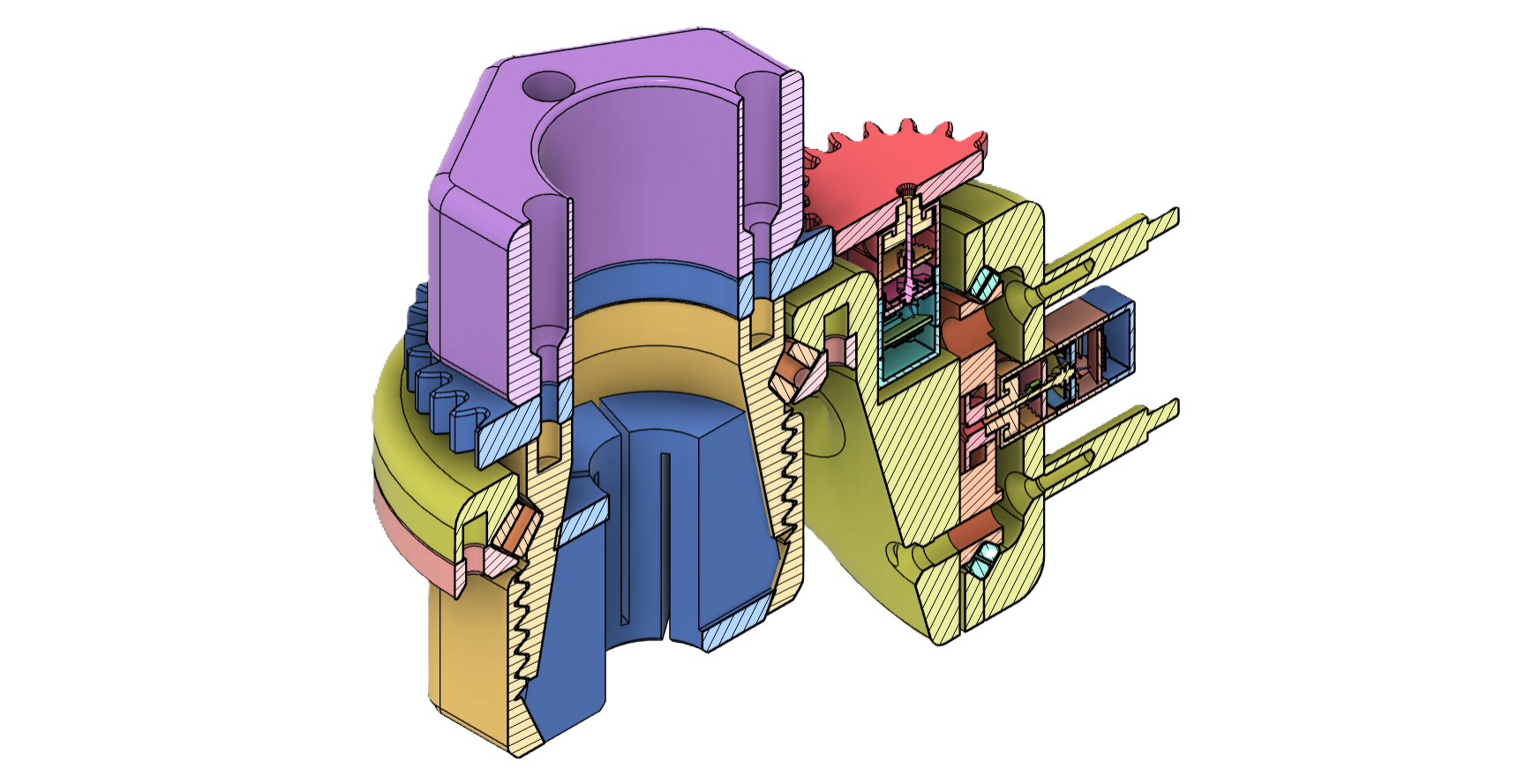
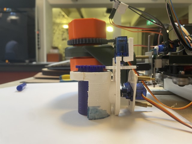
Tool holder design by Sven Dekker
Here you can find the interactive tool holder design documentation by Sven Dekker.
After completing a successful internship at Waag Futurelab in Amsterdam, I was hired as a freelancer to further develop a tool holder they were working on. My focus was on optimizing its functionality and design. The project, which lasted about a week, was driven by an upcoming Open Day where the updated tool holder was needed. During this time, I applied my technical expertise and deepened my skills in designing a product specifically for 3D production and easy open-source fabrication.
The ultimate goal is to create an interactive, universal tool holder that seamlessly integrates composite motions with user input and allowing for easy tool interchangeability.
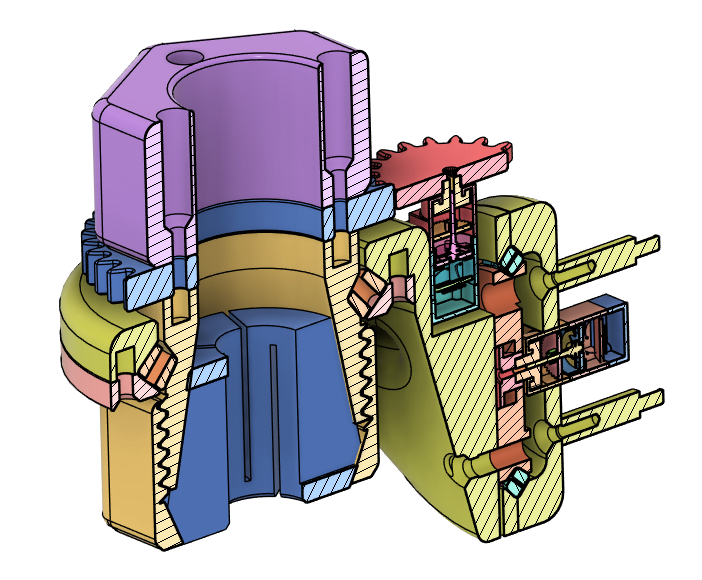
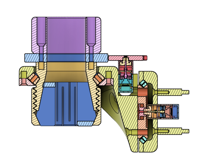
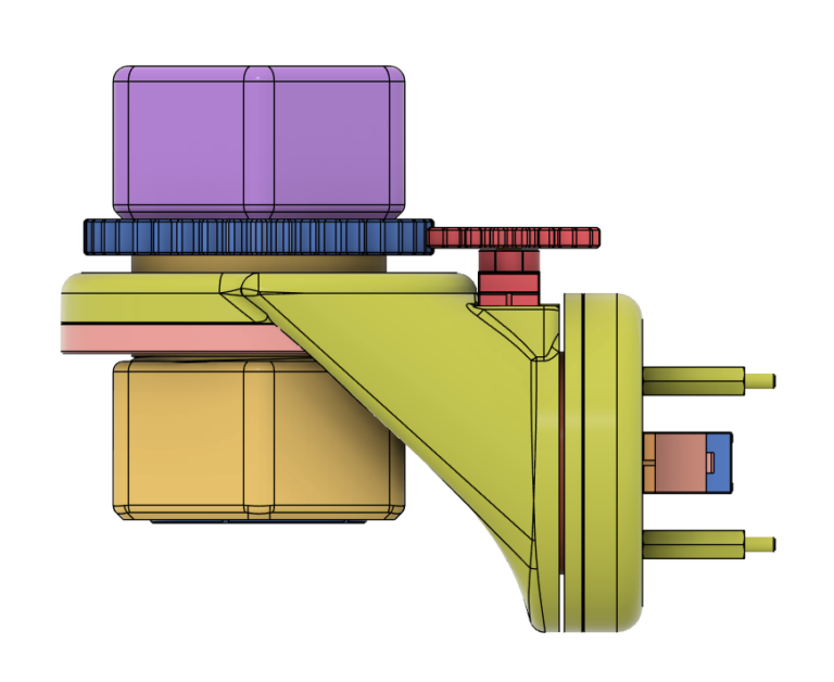
Several iterations have been made, with the final iteration visible in Figure 1. This iteration closely followed the design criteria.
Issues Encountered
-
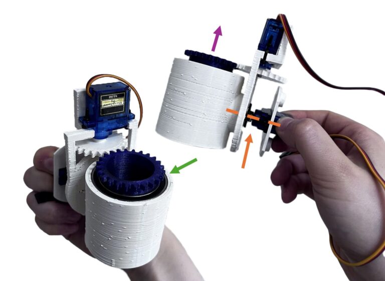
Sturdiness: The design lacks sturdiness, as indicated by the orange arrow in Figure 1. All weight and pressure from the tool are concentrated on the servo motor axis, leading to stability issues.
-
Revolving Cylinder: The revolving cylinder was not properly mounted. Under upward pressure, shown with the purple arrow in Figure 1, it tends to pop out of place.
-
Bearings: The use of store-bought bearings is a limiting factor due to their expense and limited size options, as shown with the green arrow in Figure 1.
-
Self-Centering Mechanism: The centering is achieved by clamping with sponges, but this method lacks precision, as demonstrated in Video 1.
Despite these issues, the design shows promise. The technical concept appears to work, as demonstrated in Figure 1. Further development and refinement are needed, preferably with the assistance of someone skilled in technical drawing.
Research
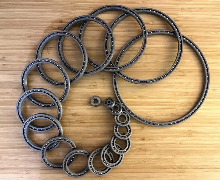
After identifying the issues in the previous iterations, I immediately recalled a past project I worked on called “Load-bearing Slip Ring”. You can read more about this project here. A 3D-printed bearing, like the one from stocki_occ by thegoofy on Thingiverse, can address three of the four major problems:
- Load-bearing: It can handle the load on the orange axis.
- Mounting Points: Custom bearings can be designed with mounting points for the revolving part.
- Customizable Dimensions: With 3D printing, bearings of any dimension can be created.
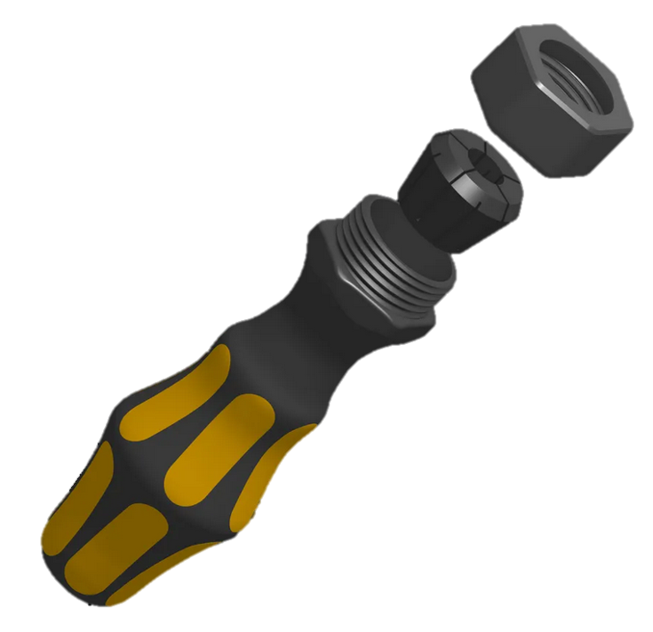
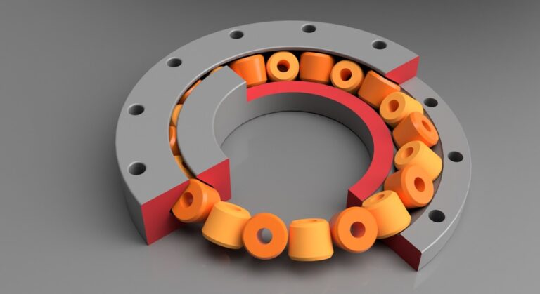
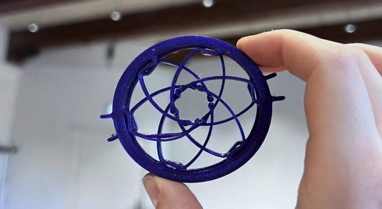
For the fourth issue (self-centering mechanism), I conducted secondary research and found a 3D-printable collet clamping system from dodasch on Printables. By printing collets of various diameters, a wide range of tools can be accommodated.
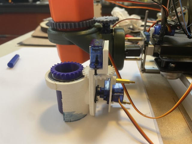
Updated Design
With a comprehensive understanding of the project, I envisioned a clear path for improvement. Building on the solid foundation laid by previous iterations, the first iteration of the updated design worked from the start and encoutered only a small hikup with the bearing, which made the overall development process smooth and efficient.
The issue I encountered involved a 3D-printed bearing with spacers that were too large, preventing the bearing from rotating. This was resolved by removing the spacers. While troubleshooting, I discovered a better 3D-printed bearing, which I will discuss further in the recommendations.
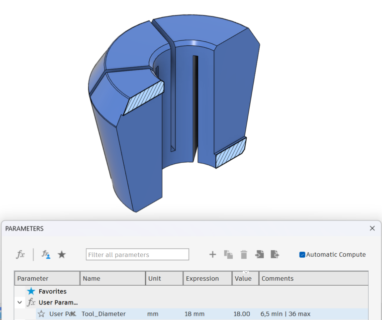
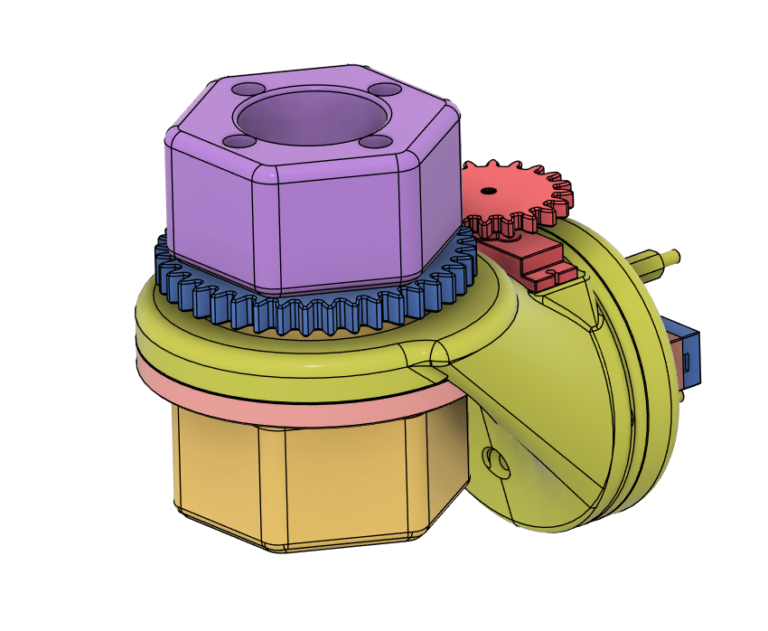
To use the collet system mentioned in the Research I had to backward engineer the .stl file. Also the design was too small for the tool diameter criteria I had. So I changed the file, so that by changing 1 paramater tool sizes from 6,5mm to 36mm could be accomodated (Figure 2).
Final result
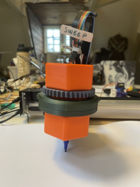
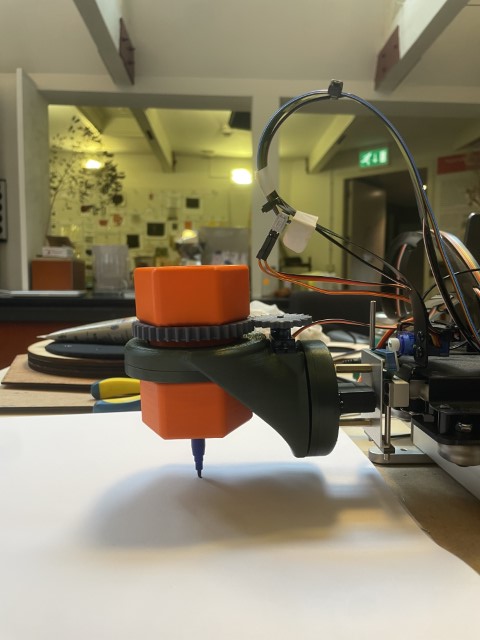
I’m really happy with how this design turned out, especially considering the time I had. During testing, it met all the criteria and was ready for the Open Day—referred to as the Open Waag by the Waag. I was also invited to observe how people interacted with Tool Holder v2. Initially, it worked as expected, but as people began customizing tools and adding more load to the servos, the 180-degree servo gearbox broke. I didn’t anticipate this issue, but I will propose a solution in the recommendations.
Below are some pictures of the final design, alongside a comparison with the previous iteration, as well as a video showcasing all the composite motions.
Recommendations
The issue I encountered with the bearing was resolved by removing the spacers. However, while troubleshooting, I discovered a better method for making 3D-printed bearings. This method is outlined in a guide by Dangineering on Printables. He uses BB gun ammo as the balls for his bearing, which is a fantastic idea because they are small and highly precise—something that’s difficult to achieve with 3D printing. Plus, you can get 1,500 of them for around €14. In future designs, I will incorporate this type of bearing.
To address the issue of excessive load on the 180-degree servo, one solution could be to implement a 2:1 gearing ratio between the servo and the rotating part. This would require switching to a 360-degree servo, so that a full 360-degree movement of the servo results in 180 degrees of actual rotation. This approach would reduce the load on the motor.
Build Guide
You can find the build guide here.