
To keep this post to the point, the focus will be on the design iterations, fabricated tool holders and their electronics. The code for the tool holders with electronics can be found on the bottom of this page.
We are approaching tool holder development in spiral development. This is a method used within the FabAcademy – one of the three academies we have running within Waag Futurelab – to keep development steps manageable and realistic. The preliminary outline of the first tool holder development looks like this:

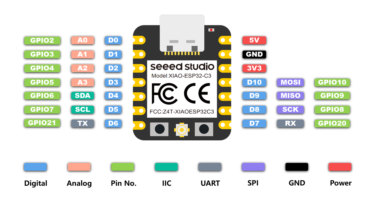
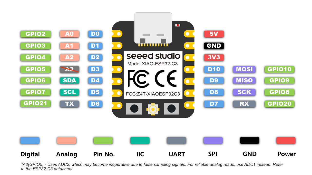
In the development of this tool holder, the focus is on creating composite motion with combinations of dragging, rolling, up and down motion, revolving and swinging. While the development of the interactive control over the motion is for the next tool holder, we are choosing our microcontroller based on our future needs which includes wireless communication. For this we will be using the Xiao ESP32C3 which has integrated Bluetooth (BLE) and WiFi. More on the electronics development can be found here.
We want to make a machine-specific attachment of a universal tool holder to make this project easier to replicate for any kind of machine. The only thing you would need to adapt would be the machine attachment; the tool holders are usable for any machine. For this, we need a connection system between the attachment and the holder. The development of this you can find here.
Note that a ‘tool holder’ in a regular CNC context may mean the collet & nut assembly (holder) that holds the milling bit (tool). We use tool holder in our context to point to our tools for plotting and the holder that keeps them in place or moves them.
Materials
The hacks don’t need a lot of special parts – they are mostly 3D printed out of PLA, so you need a 3D printer and PLA filament. The most specific are the bearings we will need to revolve – they will have to have a large (at least 30 mm inner diameter) to accomodate for various brushes. Other than that we need a couple of nuts, bolts and threaded inserts ranging from M2 to M5. For this we bought kits with various sizes.
Tool holder 1: static
Tool holder 1_1
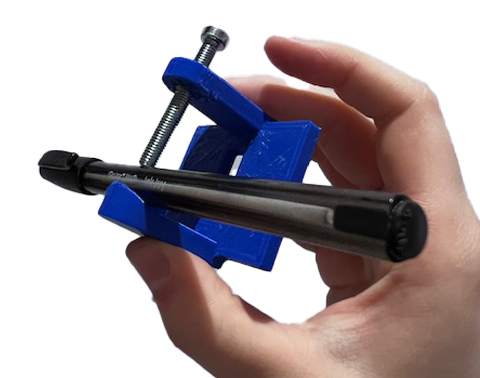
This is the first version of the static tool holder designed in Fusion 360. It’s a simple design with one side for a tool to lean against, and one side with a hole in which a threaded insert for an M5 bolt is placed. The bolt is then used to keep the tool in place.


Issues:
- Mounting holes (to mount on the Axidraw plate) are too small
- Unstable grip of the tool because the contact points of the bolt and the side to lean on are very small with a round tool
Tool holder 1_2
In tool holder 1_2 we addressed the issues with the first iteration. The mounting holes were made bigger and the grip on the tool is improved by increasing the contact points to two.


Issues:
- Bolt could still use better grip (as seen in the bottom photo above)
- Two points of counter grip would be beneficial
Tool holder 1_3
To improve pen holding stability, we made a small add-on to attach to the bolt as a counter, and have one more pen holder as to create a triangle of contact points, and chamfered the sides for a more sleek look and less material use.


This triangle of contact points principle is also used in the original Axidraw pen holder, but with this first static tool holder we now have a 3D printable one that we can also use with the Shopbot and that we can develop further.
Tool holder 2: rotating
The next spiral is a tool holder that can be set to a specific angle. The main goal here is to get a tool holder that we can easily set to repeatable angles, without having to dismantle the entire tool holder.
The rotatable pen holder in the Plottybot project is a good reference since it works with a simple mechanism using two parts to set repeatable angles as can be seen in the images below.


We took the same mechanism of aligning positively and negatively extruded circles and applied this to the stationary part connected to the machine attachment (negative side) and the rotating tool holder (positive side). Below you can see a visualisation of the rotating tool holder design and rotation in Fusion 360.
This spiral now consists of two parts: a stationary machine connection and a rotating tool holder connection. Together they are called the rotating tool holder. The two parts are easily aligned and kept in place with a bolt and nut. When mounted onto this Shopbot machine attachment, the bolt is sandwiched between the machine attachment and the stationary machine connection. By loosening and tightening the nut that secures the rotating tool holder connection, you can change the angle easily. For the Axidraw, the nut is on the back since there is no back plate to keep the bolt in place, but changing angle is still easy.


Tool holder 3: revolving
Lost parametricity in the design file
This is the first tool holder that needs to incorporate electronics. This is a big step compared to the previous iterations, and it basically abandoned the previous tool holder design, keeping only the machine attachment part intact. A decision had to be made regarding parametricity versus freedom in experimental tool holder design. One of the plans was to keep the working file in Fusion 360 very neat and parametric for future shareability with the maker community, but this ambition was abandoned to allow for more freedom in developing the new spirals. We could have also decided to work in separate files, but it was more convenient to work in the file with the correct measurements and designed parts that we wanted to reuse. This means that while the exported files are useable and shareable, the working file for tool holder 3 has lost its parametricity and is a bit of a mess. Good to note though is that the previous two iterations are still parametric and shareable – Fusion 360 has version history, so they are not lost.
Design challenges
The main challenges with this spiral are:
-
How to keep a tool centered when the tool diameter is variable? Most examples with rotating tools have a set diameter and/or a very small diameter. It would be best if we do not need a different adapter every time we use a new tool. It would also be best if we have a tool holder that is wide enough to accomodate thick brushes – especially brushes with internal reservoirs can be pretty big in diameter.
-
How to rotate a tool that can have any length? We cannot rotate something from the top, like has been done in examples we’ve found during our machine hacking research (where tools are directly mounted to a motor) and during the Fabricademy machine hack, because this needs a significant height above the material. This is easy to achieve for the Shopbot, but not so much for the Axidraw unless we extend the legs of the machine depending on the tool used, which is not very convenient. Another issue is that holding a tool only at the top did not prove to be very stable during the Fabricademy machine hack.
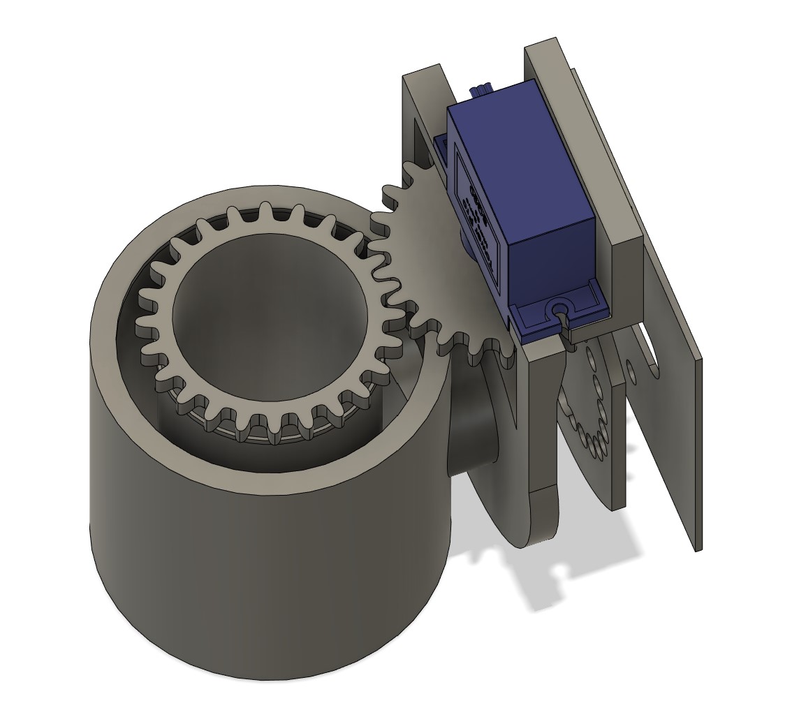
To tackle these issues, we decided on a mechanism where the motor is placed on the side of the tool holder, and the revolving motion is transfered 1:1 with a gear to a geared revolving cilinder that is placed in a larger stationary cilinder attached to the machine. Between these two parts two large bearings are placed. The revolving cilinder rests on top of the bearing with a small ridge, to align the top with the servo motor gear. We ordered bearings of two large diameters: 30x42x7mm and 40x52x7mm. The larger ones did not arrive, so for now we used the smaller ones.
The design now consists of four printed parts (the fifth being the representation of the Axidraw mounting plate) which you can see in the revolving tool holder 1_1 below.
- Non-revolving tool and motor holder with rotating connection
- Revolving cilindrical tool holder
- Servo motor gear
- Stationary machine connection (the same as in the rotating tool holder)
As a sidenote: it’s getting more and more complicated to give meaningful names to parts.
Revolving tool holder 1_1
In the first iteration, the servo motor was not properly centered, so the servo gear bumps into the side of the motor holder, so the tool and motor holder had to be reprinted.

Revolving tool holder 1_2
In the next iteration 1_2 this is fixed.
However, there is too much play between the teeth of the servo gear and the cilindrical tool holder.

This can be fixed by either bringing them closer together in the tool and motor holder or by making the gears a little bigger. Reprinting the tool and motor printer takes a long time, so we went for option 2. Unfortunately for us, the parametric gear design was not as parametric as we thought, since it breaks when you try to change parameters, and it was impossible to change the shape of the teeth in the design itself. A (not so elegant) workaround was to scale the teeth on the cilindrical tool holder, which is what we did; this fixed the problem. Here the assembly can be seen in motion:
The servo gear is not very stable. A solution would be to either print a thicker gear or to switch to a DC motor. Tightening the gear better also helps a lot, so it will do for now. We tried it out immediately:
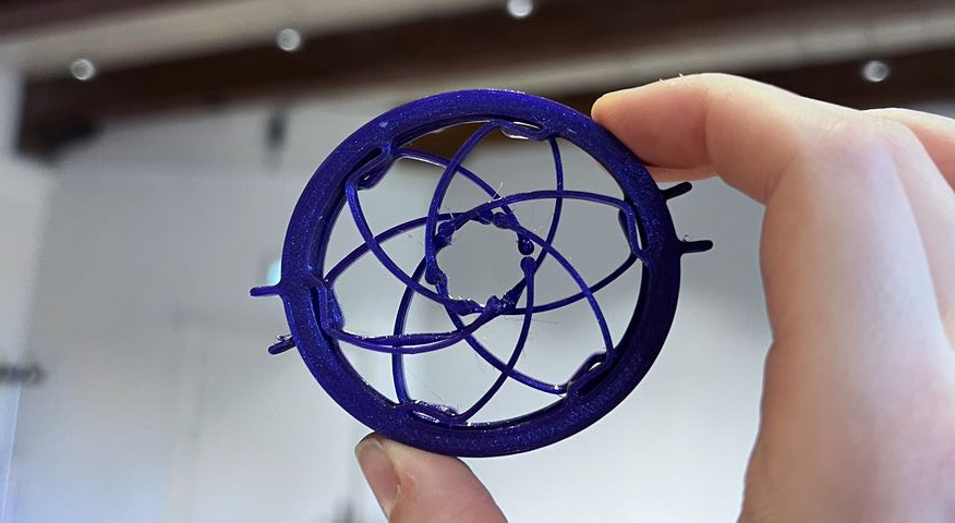
The current revolving tool holder design does not include a proper way to secure tools yet: we used isolation foam as a temporary spacer which works pretty well, but isn’t very good at perfectly centering tools as you can see in the video. We started researching various options to include in future iterations. This compliant iris mechanism (found on Thingiverse) could be an interesting direction.
Tool holder 4: up and down
We decided to skip this tool holder for now, because we are controlling up and down movement primarily in the machine motion. Implementing a swinging motion was easier to do and would give more result in composite brush motion. Up and down will still be implemented in the tool holder, but after the swinging tool holder.
Tool holder 5: swinging
Swinging tool holder 1_0
To turn the tool holder into a swinging tool holder, the stationary machine connection has to be modified to make room for another servo motor. This is easily done by taking out a servo motor-sized rectangle and mounting holes as seen in the design below. Centering the servo gear with respect to the tool holder isn’t really important, since the starting point on the material is easily changed.

To try it out, we combined it with a failed earlier print of a revolving tool holder, which includes two threaded inserts to center tools with bolts (this does not work very well). The servo motor is connected to the improv tool holder with two small screws through the servo horn.

Now, to bring the swinging and revolving tool holder together:

This tool holder is the final version of the first tool holder development round, apart from some manual hacks to try out some brush securing alternatives (chopping away part of the cilinder and adding threaded inserts and grub screws to tighten brushes).
Electronics
Bill Of Materials
In the final spiral, the electronics for tool holder 1 consist of:
| Type | What kind | Amount |
|---|---|---|
| Microcontroller | Xiao ESP32C3 | 1 |
| Servo motor (180 degrees) | 9G S90 Micro Servo 180 | 1 |
| Servo motor (360 degrees) | 9G S90 Micro Servo 360 |
1 |
| Connections | Ribbon wire and jumper wires |
plenty |
| Mounting | Breadboard, protoboard |
1 |
| Interaction | Slide potentiometer |
2 |
Revolving tool holder
The revolving tool holder consists of a 360 degrees spinning servo motor and an ESP32C3. In the first try-out, we use a set speed.
Code
This is the code used:
const int servoPin = 2; // Define the pin connected to the servo

void setup() {
  pinMode(servoPin, OUTPUT); // Set servo pin as output
}

void loop() {
  analogWrite(servoPin, 150); // Set the speed
}
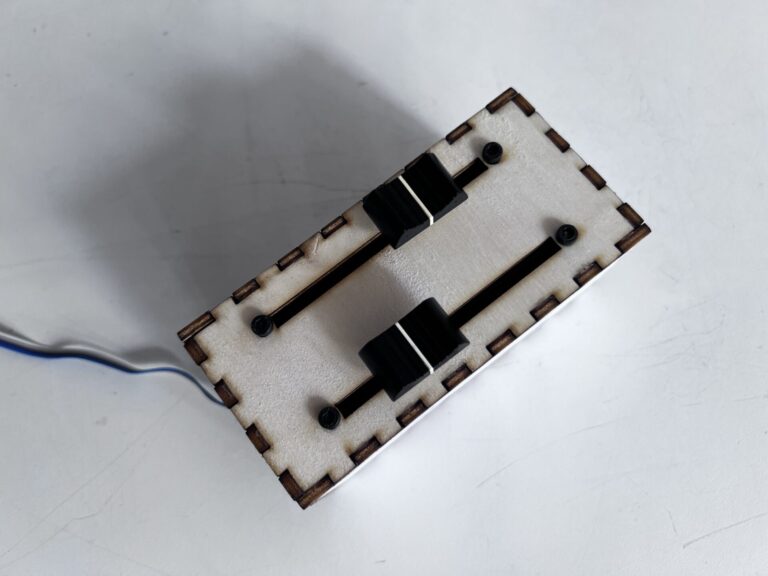
Interactivity
We are working with the Xiao ESP32C3, because it has integrated wireless connectivity options: BLE and WiFi. This makes it suitable for future wireless input or (haptic) output devices. For the first interactive device prototype, we are using a wired option to play around: using a slide potentiometer to control a 360 degree servo motor.
Revolving
The code of the initial test is very simple, mapping the analog potentiometer input to servo motor speed. This is the code for revolving one servo motor with one potentiometer.
const int servoPin = 2; // Define the pin connected to the servo
const int potPin = 3;   // Define the pin connected to the potentiometer

void setup() {
  pinMode(servoPin, OUTPUT); // Set servo pin as output
  pinMode(potPin, INPUT);    // Set potentiometer pin as input
}

void loop() {
  // Read the position of the potentiometer
  int potValue = analogRead(potPin);

  // Map the potentiometer value to the servo speed range
  int speed = map(potValue, 0, 1023, 120, 255);

  // Set the speed of the servo
  analogWrite(servoPin, speed);

  // Optional: Add a small delay to prevent rapid changes
  delay(100);
}
Revolving and swinging
For the second interactive test, we used the second slide potentiometer to control a 180 degree back and forth swinging servo motor.
#include <ESP32Servo.h>

// Revolving servo control
const int servoPin = 5;  // Define the pin connected to the servo
const int potPin = 2;    // Define the pin connected to the potentiometer

// Swinging servo control
const int servoPin2 = 4;  // Define the pin connected to the servo
const int potPin2 = 3;    // Define the pin connected to the potentiometer
Servo myServo;            // Create a servo object
Servo myServo2;           // Create a servo object
int angle;                // Variable to store the servo angle

void setup() {
  // Allow allocation of all timers
  ESP32PWM::allocateTimer(0);
  ESP32PWM::allocateTimer(1);
  ESP32PWM::allocateTimer(2);
  ESP32PWM::allocateTimer(3);
  myServo.setPeriodHertz(50);  // standard 50 hz servo
  pinMode(servoPin, OUTPUT);   // Set servo pin as output
  pinMode(servoPin2, OUTPUT);  // Set servo pin as output
  pinMode(potPin, INPUT);      // Set potentiometer pin as input
  pinMode(potPin2, INPUT);     // Set potentiometer pin as input

  myServo.attach(servoPin);    // Attach the servo to its pin
  myServo2.attach(servoPin2);  // Attach the servo to its pin
  Serial.begin(115200);
}

void loop() {
  // Read the position of the potentiometer
  int potValue = analogRead(potPin);
  int potValue2 = analogRead(potPin2);

  // Map the potentiometer value to the servo speed range
  int speed = map(potValue2, 0, 4095, 0, 150);
  angle = map(potValue, 0, 4095, 0, 180);  // Map potentiometer value to servo angle range

  // Filter results
  angle = angle / 20;
  angle = angle * 20;

  // Set the speed of the servo
  myServo.write(speed);   // Set the servo angle
  myServo2.write(angle);  // Set the servo angle


  Serial.print(potValue);
  Serial.print(" and the filtered value for the speed ");
  Serial.println(potValue2);

  Serial.print("angle ");
  Serial.println(angle);
  Serial.print(" and the speed ");
  Serial.println(speed);

  delay(10);  // Add a small delay for stability
}
Troubleshooting
We ran into some issues here, relating to:
- Broken servo
- ESP32C3 cannot use ADC2 which is attached to the pin we had one of the potentiometers on. This has since been corrected on the ESP32C3 documentation page:
Tool holder electronics: considerations for further development
For the revolution of the brushes we are using a servo motor that can rotate 360 degrees continuously in both directions, in contrast to the regular limit to the rotation angle that servo motors often have. The servo motors are easy to use, but its motion is not super smooth. It may be an option to switch to DC motors, using a DC motor driver like done here. The issue is versatility though, because with a DC motor we cannot do accurate position control, which a servo motor can – and although a revolving servo motor cannot hold a position either, it can be replaced with a regular servo motor without changing the design of the tool holder (drop-in replacement). Another things we can do to improve the servo motor functionality is to replace the plastic gear servo with a metal gear servo.