
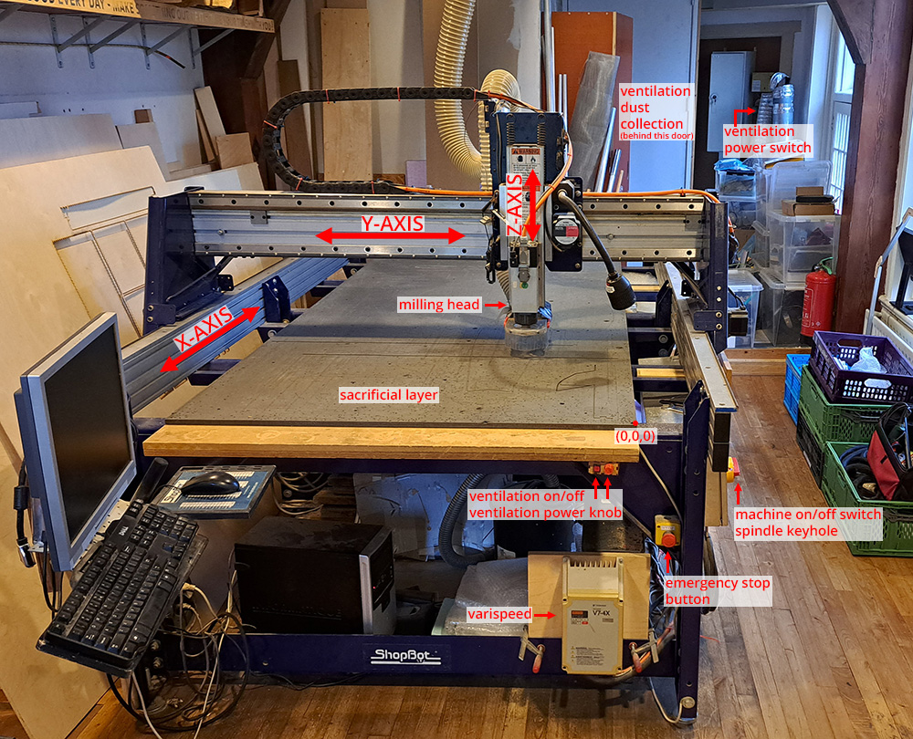
One of the machines we are developing hacks for is the ShopBot, a versatile CNC router designed for large-format subtractive fabrication. It’s commonly used for cutting wood, foam, plastic, and soft metals, and it’s capable of both 2D and 3D operations. You can find the safety instructions and machine operation steps on the Fablab documentation page. For the purpose of our machine hack, we will not be using the spindle and ventilation system, which makes machine operation a bit easier (and less dangerous).
While Waag’s ShopBot is operated through VCarve Pro, a CAM software that generates machine-readable toolpaths, this standard workflow presents limitations when working experimentally. For more dynamic, custom fabrication logic, we explored how to bypass the conventional CAM software and script our own machine code directly within Grasshopper.
We started with the standard workflow to understand the baseline mechanics of the ShopBot and its motion logic.
Getting Started: VCarve Pro Workflow
Our first test involved using the conventional VCarve Pro → ShopBot Console pipeline.
Steps in VCarve Pro:
-
Design the geometry to be cut or engraved using any vector software or directly within VCarve.
- Create Job setup
- Make sure to use the upper surface of your material as the Z zero location.
- 0.5 mm thickness for material is enough for the purpose of the job of painting.
- XY datum position is really important. This will determine the XY position of the milling head in reference to your material. It is good practice to always use the same corner as it reduces possibility of mistakes.
-
Import the vectors into VCarve Pro
- Move your vectors to fit in the material area
-
From the Toolpath Operations, select 2D PROFILE TOOLPATH. We will not cut, but this toolpath type is the closest approximation that VCarve Pro can do to a drawing.
- Make the start depth 0.0mm
- Make the cut depth 0.01mm
- Edit the tool (see the following page for the values).
- Machine vectors should be ON the drawing vectors.
- Edit the Tool with the following settings:
-
Change the diameter to 0.1 mm. This diameter is only for simulation purposes, as we are not actually cutting into a material. You can use this diameter no matter what type of brush you use.
-
Feed rate is the speed at which the machine will move. We tested with 90 and 120, which were both good speeds. We did the majority of the drawings with the 90.
-
Hit OK.
-
-
In the main screen, select all the lines you want to draw and hit CALCULATE. A small simulation of line starting points (square dots) and line drawing directions (arrows) will appear.
-
Now Profile 1 is ready.
-
Making sure there is a checkmark next to the toolpath you want to see, hit Preview Toolpath. It is good practice to always preview the toolpath to eliminate mistakes.
-
When you simulate the toolpath, the lines are color-coded:
- Red: Movement of the machine above the material
- Green: Plunge of the tool
- Blue: Movement of the machine on the material
-
After simulating the movement, hit Close.
-
-
Now the toolpath is ready go be drawn. You need to convert the toolpath information generated in VCarve Pro to machine language. The machine language of Shopbot is Shopbot code.
To do so, select Save Toolpath. The toolpath will be saved as .sbp (ShopBot’s proprietary format).
Steps in ShopBot Console:
On the Shopbot Console, you command and communicate with your CNC milling machine.
- You can open the KeyPad by hitting the K key on your keyboard. If you hold the computer screen perpendicular to your shopbot, you can align the arrow key directions. – Left, right arrows: x-axis – Up, down arrows: y-axis – Page up, page down: z-axis Go to the desired job origin on your material with the keys.
-
When you are in the job position, take note of the X and Y locations from the Position Pane. This can help you with restarting your job from the same location if your job gets cut short due to a problem. Afterwards, Go to:
ZERO> zero [2] axes (X &Y)
-
As you will notice, the X and Y positions in the Position pane are 0 now. We set the job origins.
-
To zero the z-axis, bring your metal plate underneath your milling bit. Touch the metal plate to the milling bit a few times to check if inp 1 turns momentarily green when the plate and the bit are in contact. This will ensure that the milling head stops when it touches the plate.
-
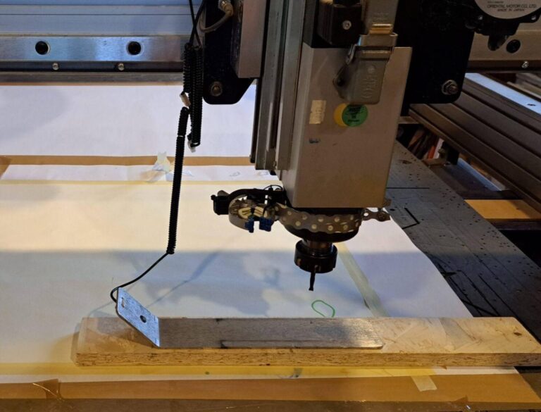
Place the plate exactly underneath the milling bit. Notice that we put a block of wood under the plate, this is a measure to keep the milling bit in place while drawing with a custom brush. The block of wood ensures that the milling bit will keep a distance from the material surface equal to the thickness of the wood.
-
Hit the Zero Z button to start zeroing the Z-axis. When the command finishes, it will prompt a reminder to put the plate away, and make sure to put the wooden block away too. Notice the z position is 5.996 now. It means that after zeroing the z-axis, the milling head moved 5.996 mm above the material surface to create a safe starting distance.
-
To be able to put our brush in the correct height, we need to move the z-axis to 0.000. To do it: Hit the K key and manually type 0.000 next to Z and hit GO TO.
-
Now the milling head is in Z 0 position. You will notice there is still a distance between the surface and the tip of the milling bit. This distance is the safety distance we created with the wooden block.
-
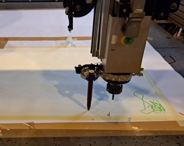
Put your brush in the holder attachment. You need to have good contact with the surface of the material. This is the height it will paint from when the job starts. Make sure that the brush is tight, and it cannot move with the drag of the machine from one point to the other.
-
To bring in a shopbot code file, go to: FILE > PART FILE LOAD
-
Select your file. And hit Open. The file format of shopbot code files are .sbp.
-
When you are ready, press START
Beyond the Interface: Writing Our Own ShopBot Code
To gain more control over the ShopBot’s behavior, we began developing custom motion code outside the VCarve ecosystem. Writing ShopBot code directly allows us to:
-
Insert custom pauses during cutting or movement
-
Trigger actions based on spatial locations (e.g., pause at corners)
-
Coordinate toolpath sequences in new ways
-
Integrate machine motion into parametric workflows
For this, we turned to Grasshopper, Rhino’s visual scripting platform, where we could generate geometry and toolpaths parametrically—and translate them into machine instructions.
Custom ShopBot Control with Grasshopper
In our hack, we bypassed VCarve Pro entirely by generating custom .sbp code within Grasshopper. This approach allowed us to craft a machine logic specific to our design and fabrication goals, rather than adapting our designs to fit within predefined toolpath strategies.
Why Grasshopper?
-
We could work parametrically, adjusting geometry and motion rules on the fly.
-
We had full control over machine units, cut order, feed rates, and other parameters.
-
We could embed custom SBP commands (e.g., PAUSE, JZ, MS, M3) to choreograph tool movement and interaction.
This setup enabled us to explore alternative fabrication logics, turning the ShopBot into a programmable tool that could respond to design intent, material behavior and desired outcomes.
How to Set Up Your Custom Workflow
-
Familiarize yourself with ShopBot code syntax (Command Reference)
ShopBot uses its own scripting language (.sbp files). Key commands include:
-
J2 for jogging to coordinates
-
MS for to move 3 dimensions
-
PAUSE to stop for manual intervention
-
CG to call custom macros or secondary files
-
-
Build your geometry and motion logic in Grasshopper
-
Use tools like Divide, Polyline, or Interpolate to define toolpaths.
-
Map these paths to machine coordinates, including depth (Z values).
-
-
Translate Grasshopper output to SBP code
-
Use custom scripts or plugins (e.g., Squid, Human, or your own Python/C# components) to format your commands line by line.
-
Export the result as a .sbp file.
-
-
Run the custom code on ShopBot
-
Place your .sbp file in the correct folder.
-
Open the ShopBot Console and run it like a standard file—only now, you control every move.
-
Shopbot language
To operate the machine, you need to speak the same language as the machine. In the case of the Shopbot, this is a specific flavour of G-code called ShopBot Code. During the Fabricademy Open Source Hardware week in 2023, Aslı Aydın Aksan explored the generation of this code using Grasshopper.
Understanding the Shopbot code (.sbp file):
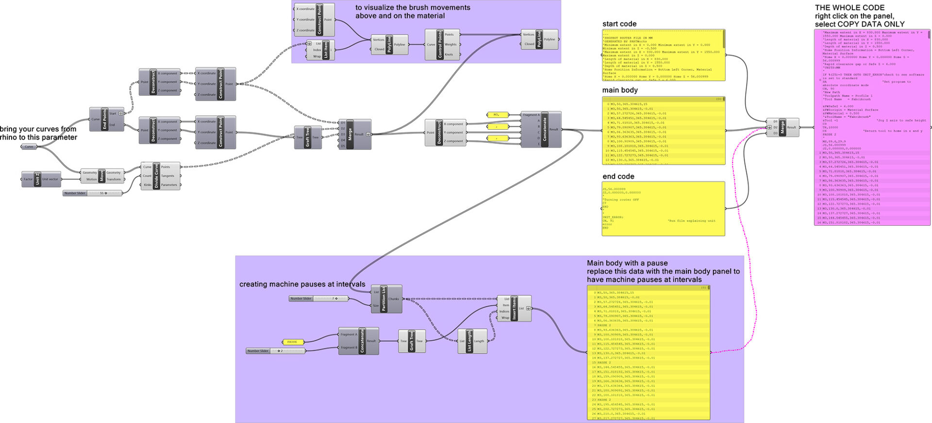
Shopbot code language is similar to gcode language for 3D printers. Every line is a specific command for the machine to execute. It has the following parts:
- Starting code: Defines the material size, starting coordinates, tool size, material depth, travel speed, etc.
- Main body of the code: Defines the travel coordinates (x,y,z coordinates) of the shopbot head.
- Ending code: Travels the head of the shopbot to the starting coordinates and turns of the router.
To be able to understand more about the commands, please refer to this document: ShopBot Code