

This blog post describes the development of the water pump system using three 5V aquarium pumps that can be turned on or off with buttons. This is the precursor to the Dye and motion output system, which uses a more powerful 12V pump that can be controlled more precisely.
Considerations
The first two tool holder developments have been focused on moving towards interactivity. They have not been focused on a clear way to introduce mediums. We explored different options: feeding paints manually in between ink deposition, using brushes with internal reservoirs and placing paint directly on the canvas so the tool can move over it and spread it. We have not explored an external spot where the tool travels to in between to ‘recharge’ medium, since this needs a significant change in the code to move the machine. This has worked to some extent, but it has definitely not been ideal. Now that we want to move to printing with bio-based mediums, we need more control and reliability.
In our experiments using the static tool holder and an IV drip with mordant pastes, we are missing:
- proper downward pressure
- consistent and controllable flow of the medium
- stable tool holding
This is what we are adressing in the current tool holder iteration. This is a branch of the first tool holder development; the second tool holder development is the interactive/haptic development. We are going to explore IV drip mechanisms (manual and digital control) as the method to introduce the medium.
Up and down
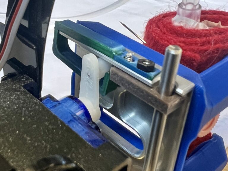
We are looking for a tool holder that mainly goes up and down, but doesn’t revolve. Rotating functionality can be useful, but it’s not our biggest need. Up and down on the AxiDraw is easy if you take over the servo motor that is on there; it’s just a matter of plugging it out of the Axidraw and into the custom board. However, it does not transfer to other machines like the Shopbot so we still need an up and down motion module for that. There is a downside to make it for the AxiDraw, since it’s already there and it would make it even more heavy and bulky. However, the way it works on the AxiDraw does not provide a lot of downward pressure because the plate is hanging on the servo motor ‘pusher’. This is something that is needed often. A linear actuator may be better because then the brush can’t push the plate up. Another solution could be to make a sort of guide for the servo motor pusher. Since that is the simpler solution, we started with that one first. Below you can see the first version of the servo motor clip:
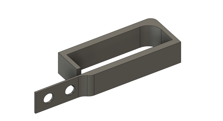
This first version held up for a bit, but it can flex easily so if you try to press too hard, it just bends.
Up and down on the Shopbot would need a simple linear actuator module. We’re making one that integrates it into the machine-specific attachment. You can read more about this hack here.
Kant Twist tool holder & hollow tool
The last version of the static tool holder has 3 contact points, but it’s a bit finnicky to tighten and the tool is still susceptible to move when there is pressure applied. During the first tool holder experimentation, we already looked at alternatives, but we did not implement them.
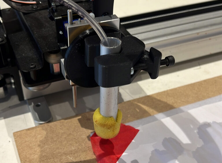
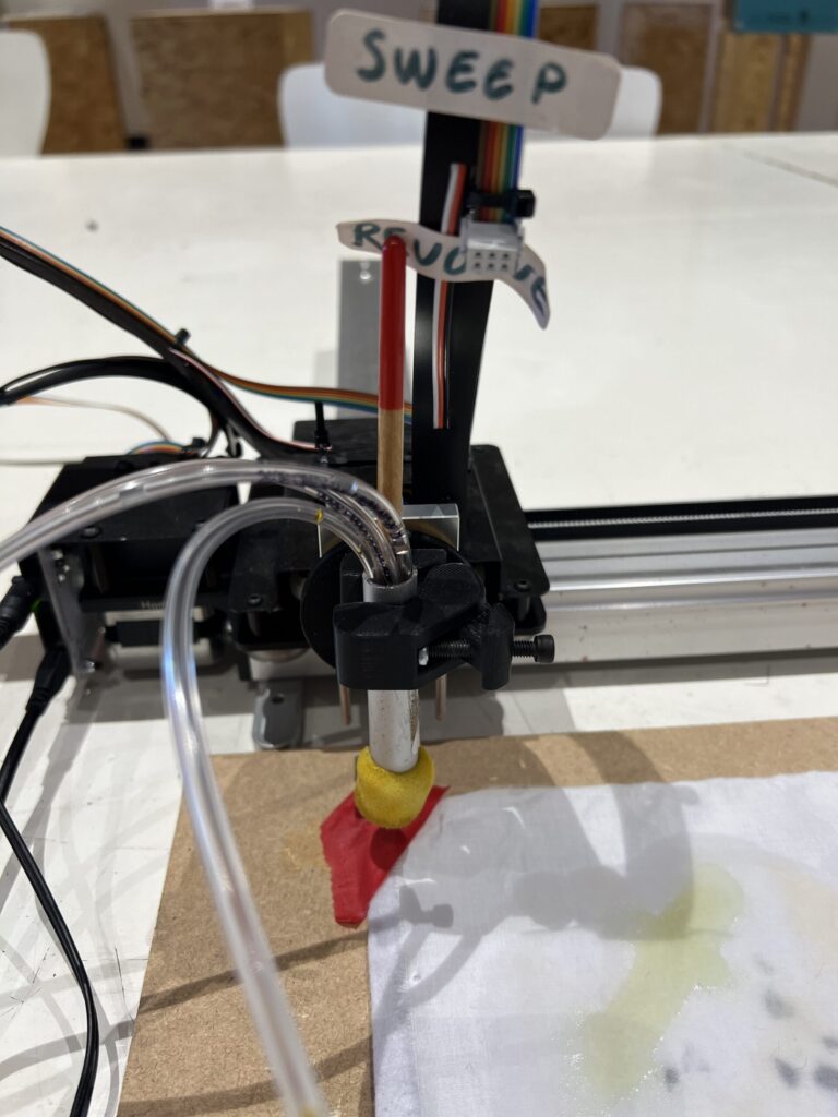
For the new tool holder, we combined the rotating tool holder with a new clamping tool. We noticed that the static tool holder clamping mechanism was not very stable with some tools, so we looked into different mechanisms and ended up finding this Kant Twist mechanism works very well. You only need to tighten one screw and it has a pretty solid grip. This tool holder in the Static Tool Holder hack.
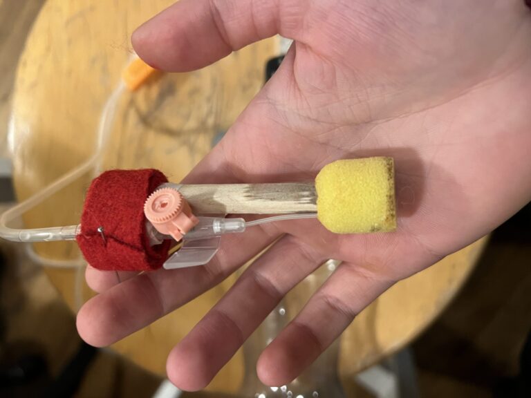
You can also see the hollow tube sponge brush that we made by taking apart a sponge brush and inserting a metal tube. More on the hollow tool development can be found here.
IV Drip
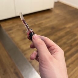
The IV drip that we have, has a needle that originally needs to go into a vein by puncturing the skin with the stiff needle around it. Then the stiff needle is taken out, leaving only a thin flexible tube inserted. In our application, the needle has to be inserted into a sponge, brush or reservoir. It needs to be easy and fast, and we want to be able to use multiple mediums in one brush, without dismantling the entire tool.
A question we need to answer here is whether the IV drip needs to work with all kinds of tools, or if should we design tools in a specific way that it connects easily to an ink depositing system. It could work to have hollow cilindrical tools for example, where you stick in the various tools. We can also have tube connectors that screw or snap onto each other easily, so you can work with one tube and swap them out while printing. We can also have a system with multiple tubes that can be controlled individually.
This tool holder has different needs and wishes that we need to address than the rotating & revolving haptic input tool holder that we have developed so far, so we are approaching this as a different development branch.
Electronic control
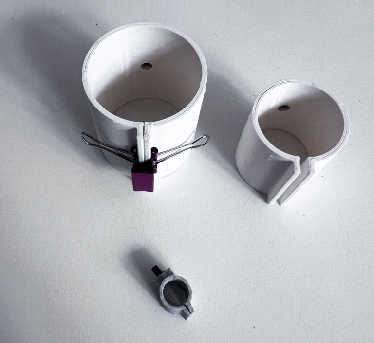
A project that Michelle has worked on before involved aquarium pumps in pots of ink, that were controlled with 3 big buttons to deposit the ink on a canvas. We are using this as a starting point, since it’s pretty close to what we would like to achieve. The project was dusted off, broken aquarium pumps where replaced and some tube converters where printed to go from thicker to thinner tubes:
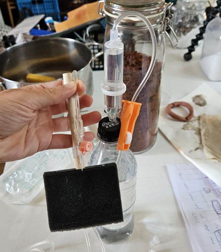
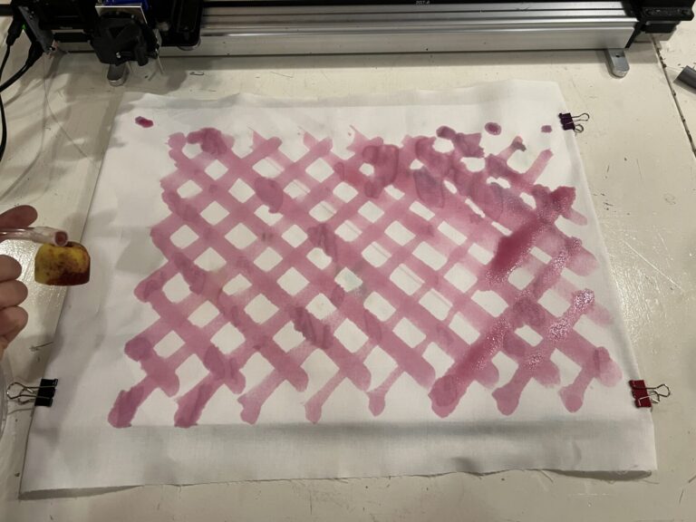
One downside to the aquarium pumps is that the amount of ink cannot be regulated in a ‘range’: the flow is either flowing or not (on or off). With the IV drip, you can manually throttle the flow with a part (the orange part in the picture demonstrating the IV drip with the bottle and the sponge brush) that ‘squeezes’ the tube. These mechanisms can probably be combined, but in the ideal case we would be able to control the flow digitally. When trying it out however, we noticed it was still easy enough to get a small amount of ink when needed. The ink stops flowing and retracts as soon as you stop pressing the button.
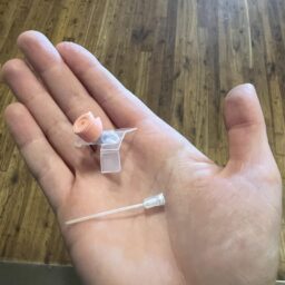
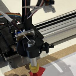
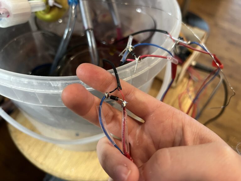
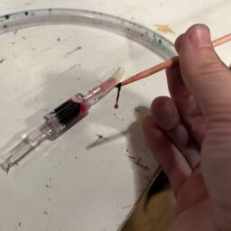
We dissected the IV drip needle, and cut off the soft end tube and printed a connector for it; it’s a bit leaky bit works for a first test.
Testing
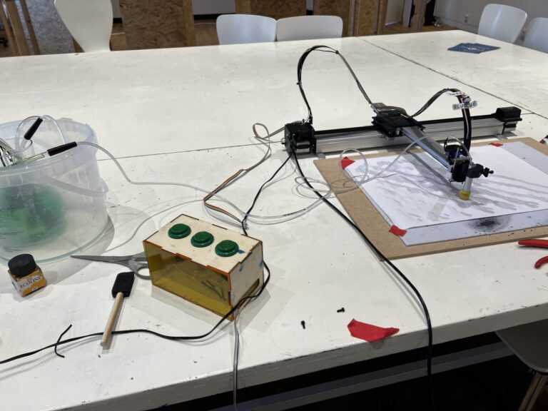
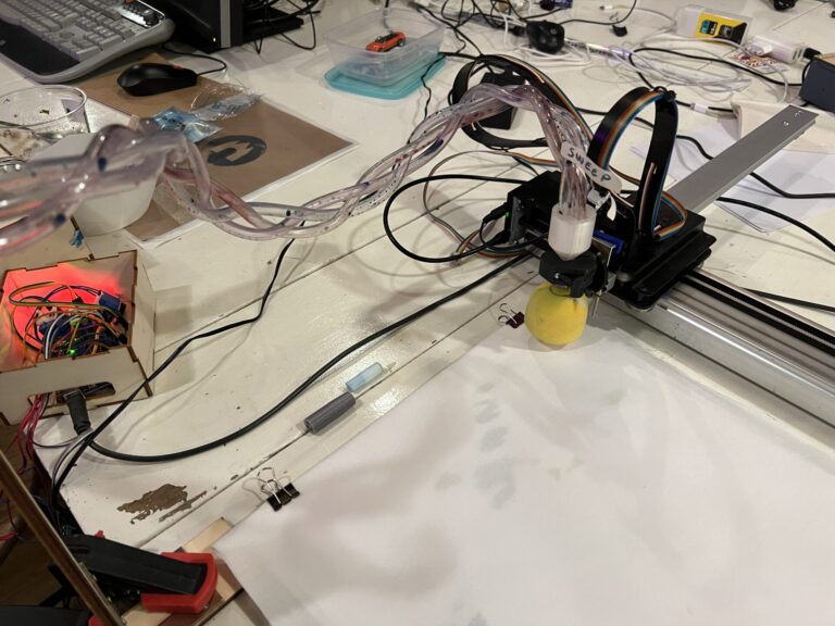
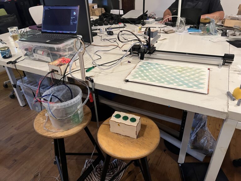
Here you can see the setup for the initial test. The laptop is placed on a chair away from the setup, since I was afraid to spill water on my computer. Liquid and electronics form a real concern, especially with all of the tubes and wires crossing and possibly intertwining.
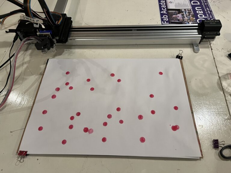
Here you can see the first test run with water with a tiny bit of ink (not enough to leave a trace on the paper). The tube was not secured, so it fell out during the process. You can also see a problem with the flow: once it’s flowing, it keeps on flowing even when the button is not pressed. This is an issue (capillary action?) I recognized from when I was working with the aquarium pumps earlier, and it can be fixed by placing the reservoirs on a lower point than where the tubes end: then the liquid can draw itself back when the buttons are unpressed. Another advantage of placing the reservoirs on a lower point, is that there is a lesser risk of knocking the reservoirs over and spilling it on the machine or the connected computer.
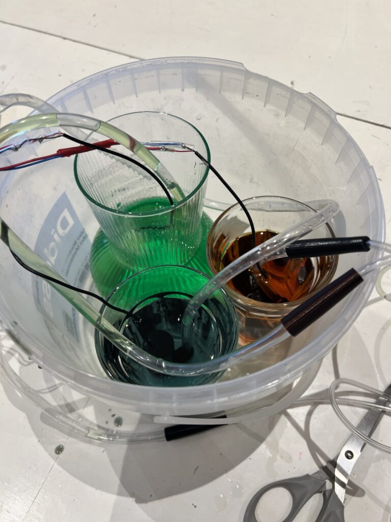
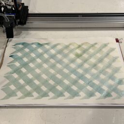
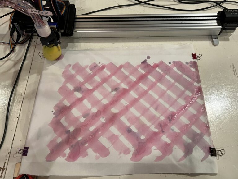
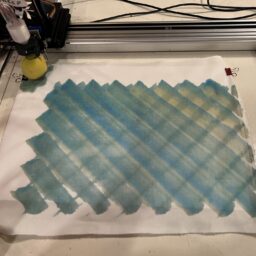
In the second test, all three tubes are connected, and there is a little bit more ink in the reservoir so you can actually see the colors (a little). The ink reservoirs are placed on a lower level than the machine, which means that the ink is drawn into the tube back as soon as a button is released. You can see that cable and tube management needs some attention, since it’s messy and dragging on the (wet) canvas.
The tubes are provisionally fixed in place with a broken brush, which works pretty well as a stopper.
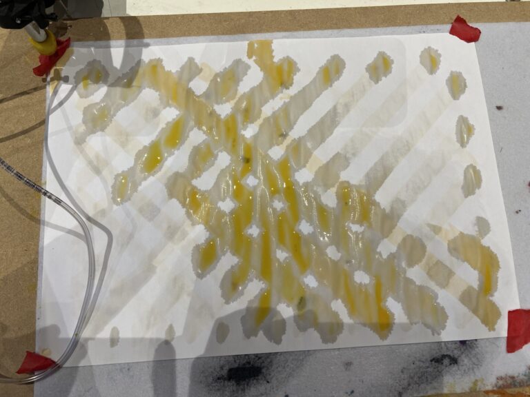
Here is the (very wet) result. It would be better if the ink was thicker, although printer paper doesn’t have the best liquid absorption either. The modifier pastes that we work with are a bit thicker, so that may already be enough.
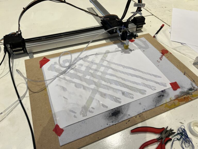
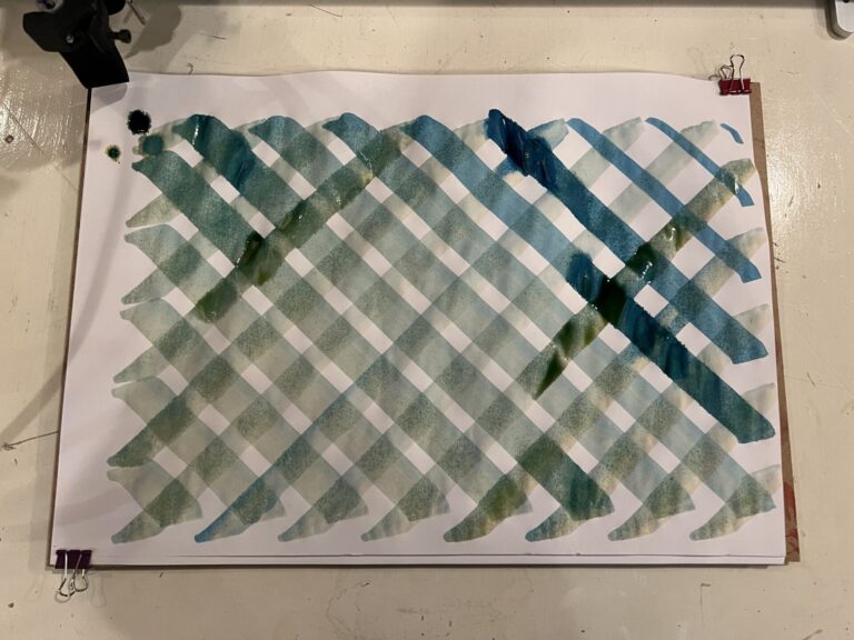
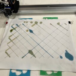
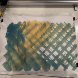
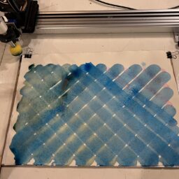
In the third test, we tried two different colors to test how accurately and easily you could switch between them. As you can see, it takes a while before the color change becomes visible after changing which button is pressed. This has to do with the distance between the reservoirs and the brush (it needs to travel about a meter) and the ink still in the sponge. The green ink is also very diluted which doesn’t help.
Although very wet, you can see two distinct colors appearing:
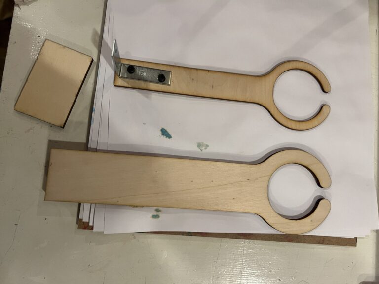
To stop the tubes from dragging over the canvas while plotting, we made this simple tube guide which elevates the tubes. The second version on the bottom is slightly higher and sturdier.
Another improvement was braiding the tubes, which also was a visually pleasing solution for cable management.
Relay false triggers
When trying thicker inks (by mixing in 1% of guar gum in weight) it became apparent that the pumps did not like this very much. I noticed that all of the relays sometimes kept clicking (triggering) when pressing only the button for the relay with the thicker ink. You can see this happening in the video below.
While working on a different project which included a flyback diode to stop current from flowing back into the system, I figured maybe that would help too in this system (since other relays were falsely being triggered), and found a similar recommendation on a forum to add a diode between the two poles of a DC motor. This seemed to fix the problem, so that’s great.
Inks mixing, travel distance and flow control
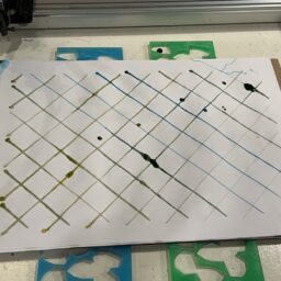
I hoped that when I made the ‘local reservoir’ in the tool that the inks would not mix (by pulling the ink in there back through different tubing) but this still happened. It also takes a while before the ink reaches the brush: when you first press the button, it can take up to about 0.5-10 seconds (depending on the viscosity of the ink) before it reaches the tool, and then it can take longer still before the brush is saturated. It’s hard to control flow when the ink reaches the tool very quickly, but it’s also hard to control flow when it takes a long time. In the current system, we cannot control the amount/speed of flow of the ink, the pumps can either be on or off. You can see exactly when the button was pressed in the plot below as the ink is immediately wetter and darker.
Multiday testing session
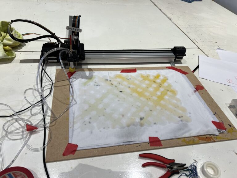
In week 44 and 45 of 2024, Michelle did various tests with diluted watercolor inks and the interactive pump system in development with the following set-up.
- An AxiDraw with canvas on the table
- A laptop on an elevation on the table to protect it from possible spills
- Three ink pots with water pumps in a bucket on a lower level than where the ink exits the tubes
- A tube guide for elevating and managing the tubes
- The button box to control the ink pumps
Multiple parametric tools were also explored in this session. You can read more about their development here.
First testing with blue and yellow ink, using a rectangular sponge brush, a thicker round sponge brush and then a narrow brush tip. In all tests you can see the struggle with ink flow.
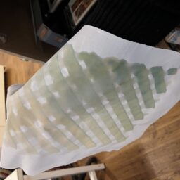
Here you can see the ink flow immediately overwhelming the brush.
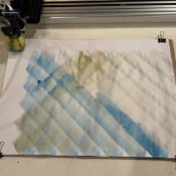
The next test is with a membrane tip taken from a Molotow dripstick. Since the membrane is much smaller in volume, color changes are quicker than with the sponge brushes, so that’s an improvement. All three colors are used in this test.
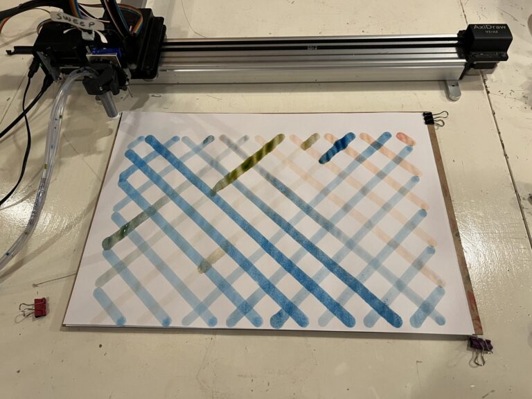
Flow control is still an issue but it’s not as bad as with the thinner brush.
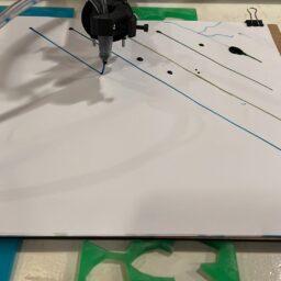
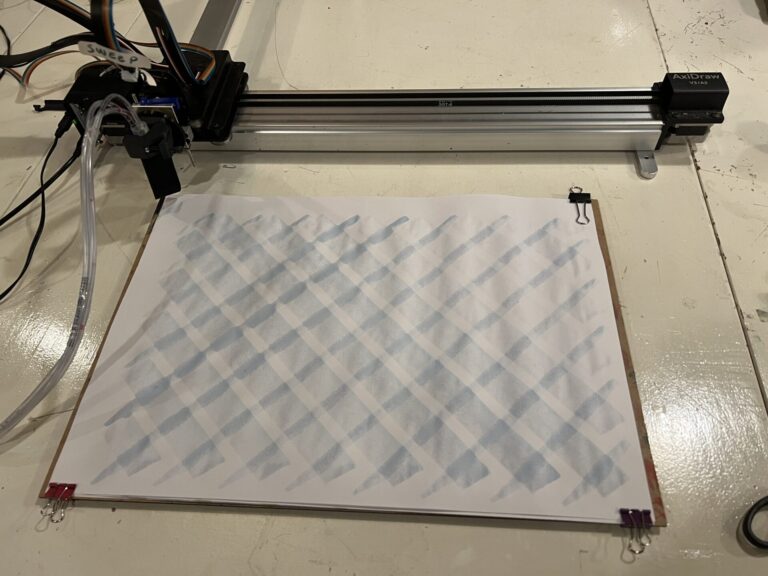
In this test, the ink is too diluted, but the flow is more consistent since no ink is sent to the brush during the plot.
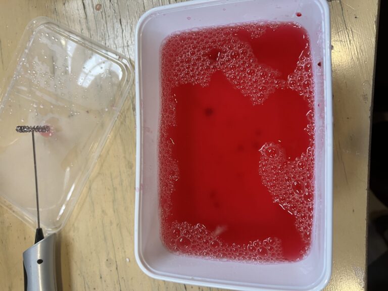
To make the ink flow more slowly and controlled, Cecilia adviced to add guar gum (1% in weight) to the ink to thicken it. I added it to the red watercolor mixture and then tried to mix it with a milk foamer. However, it took too long before I started mixing it, and some of the guar gum had already formed chunks. This would give problems later on.
The first test with this ink in the current set-up with thin tubes immediately shows bigger flow issues than before. Whereas before the ink would mainly flow too fast, now it’s way too slow. In the video below, you can see how slowly the ink moves through the tube.
Not a very succesful resulting plot.
To tackle this, I changed the thin tubes to thicker tubes, so the ink would have more ‘room’ to be pushed through the tube. Here this is tested without a tool: the thick tube is just stuck to the sponge directly with double sided tape.
You can see that the ink flows at a reasonable flow now; the sponge is dragging a bit since it doesn’t stick very well but it shows that increasing the tube diameter allows for thicker inks to flow through.
After this test, the parametric tool was updated to reflect the new tube diameter.
Using the thicker ink with the new tool holder works, but the tool was not tightened enough so the tool rotates and there is not enough downward pressure.
The result is a bit messy.
Trying it out with the unthickened water color inks shows that the flow can be overwhelming very quickly, although getting used to it (knowing when to press and when to stop) and using a material like watercolor paper as a base both help.
Valves
It could help to add one-way valves (check valves) into the tubes. If there is a valve close to the tool, you could block (mixed) back flow, and if there is a valve close to the pump, you could use this to store ink closer to the tool to decrease ink travel time. There could be both a valve in the tool itself, and a valve in each of the tubes close to the pump to combine both functionalities. Another upgrade could be to open and close the reservoir to the brush controlled with an extra motor or solenoid, but this would make the design more complicated.
We added a one-way valve close to the pumps which stopped the pumps from pulling back all of the ink as soon as the button was released. Here you can see it in action:
With the unthickened ink, it gives quite a bit of control.
However, it does add more resistance to get the ink through the tube again. It’s already hard for the pumps to push thickened inks through as it was, so that was not helpful. You can see how slow the ink moves now that the valve is in place:
Here I removed the valve for the thickened ink. The flow rate is very slow in the video. I think it’s very likely that the uneven thickness of the ink is causing issues: thicker pieces are getting stuck in the pump, valve and tube, creating a lot of extra resistance.
Another issue is the limited shelf life of inks thickened with guar gum. After about two weeks, the ink started growing mold. The pumps were still in the ink, so the pump was also moldy as well as the tube.
During later tests, we also noticed that with cochineal ink the valves would get stuck because of thicker beetle scales that weren’t crushed small enough.
Code
This is the code used to control the three pumps with three buttons.
// constants won't change
const int BUTTON_PIN1 = A1;
const int BUTTON_PIN2 = A0;
const int BUTTON_PIN3 = A2;

const int RELAY_PIN1 = A3;
const int RELAY_PIN2 = A4;
const int RELAY_PIN3 = A5;


// the setup function runs once when you press reset or power the board
void setup() {
  Serial.begin(9600);       // use the serial port
  pinMode(RELAY_PIN1, OUTPUT);
  pinMode(RELAY_PIN2, OUTPUT);
  pinMode(RELAY_PIN3, OUTPUT);

  pinMode(BUTTON_PIN1, INPUT_PULLUP);
  pinMode(BUTTON_PIN2, INPUT_PULLUP);
  pinMode(BUTTON_PIN3, INPUT_PULLUP);

}

// the loop function runs over and over again forever
void loop() {
  pump();
}

void pump() {

  uint8_t state1 = digitalRead(BUTTON_PIN1);
  uint8_t state2 = digitalRead(BUTTON_PIN2);
  uint8_t state3 = digitalRead(BUTTON_PIN3);

  Serial.println(digitalRead(RELAY_PIN1));

  if (state1 == HIGH) {
    digitalWrite(RELAY_PIN1, HIGH); // turn OFF pump
  }

  if (state1 == LOW) {
    digitalWrite(RELAY_PIN1, LOW);  // turn ON pump
    Serial.println("Button 1 pressed");
    delay(100);
    digitalWrite(RELAY_PIN1, HIGH); // turn OFF pump
  }

  if (state2 == HIGH) {
    digitalWrite(RELAY_PIN2, HIGH); // turn OFF pump
  }

  if (state2 == LOW) {
    digitalWrite(RELAY_PIN2, LOW);  // turn ON pump
    Serial.println("Button 2 pressed");
    delay(100);
    digitalWrite(RELAY_PIN1, HIGH); // turn OFF pump
  }

  if (state3 == HIGH) {
    digitalWrite(RELAY_PIN3, HIGH); // turn OFF pump
  }

  if (state3 == LOW) {
    digitalWrite(RELAY_PIN3, LOW);  // turn ON pump
    Serial.println("Button 3 pressed");
    delay(100);
    digitalWrite(RELAY_PIN1, HIGH); // turn OFF pump

  }
}